
State: NY
County:
Owner: State
Location: Urban
Spans: One-span
Beam material: Concrete
Max Span Length (ft.): 82
Total Bridge Length (ft.): 82
Construction Equipment Category: Lateral Slide
ABC Construction Equipment: Lateral Slide w/pad
State ID Number:
NBI Number: 000000001032621 and 000000001032622
Coordinates
Latitude: 41.3850288 | Longitude: -73.5594177

Bridge Description
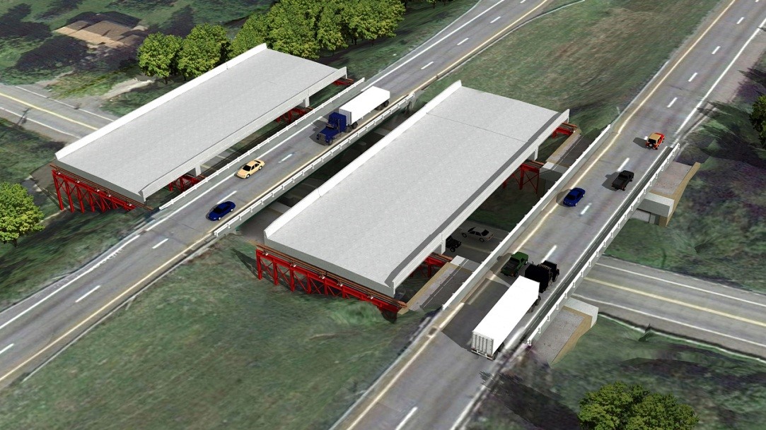
Project Summary:In September 2013, the New York State Department of Transportation replaced the twin 135-ft-long, three-span I-84 bridges using ABC techniques because only a single night closure for each bridge would be required. Closure of the roadway for 18 hours allowed for the rapid demolition of the existing bridge and slide-in of the new superstructure.
Project Location:
Interstate 84 EB and WB over Dingle Ridge Road in Putnam County, 50 miles north of NYC (2.2 MI E JCT RTS I-84+I-684)
Impact Category:
Tier 1 (within 1 day)
Mobility Impact Time:
ABC: 18-hour closure each (2 Saturday nights total);
Conventional: 2 years
Primary Drivers:
- reduced traffic impacts: avoided costly traffic delays; the innovative technique reduced delays and traffic queues by 96 percent from projects for conventional construction bridge replacement activities
- reduced onsite construction time
- improved work-zone safety
- improved site constructability
- minimized environmental impacts: protected the environment by avoiding eliminating the need for a temporary bridge
- reduced life-cycle cost and initial cost
- maintain existing alignment
- minimize business impacts
- maintain essential services
Dimensions:
Twin 82-ft-long and 57-ft wide single-span prestressed concrete NEXT D beam bridges; no skew
Average Daily Traffic (at time of construction):
38348
Traffic Management (if constructed conventionally):
If constructed conventionally: two years of detours.
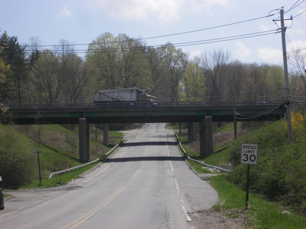
Existing Bridge Description:
Each existing 3-span steel I-girder bridge was 135-ft long and 33-ft wide on conventional concrete substructures with shallow foundations. It had two 12-ft-wide traffic lanes and two 4-ft-wide shoulders.
Replacement or New Bridge:
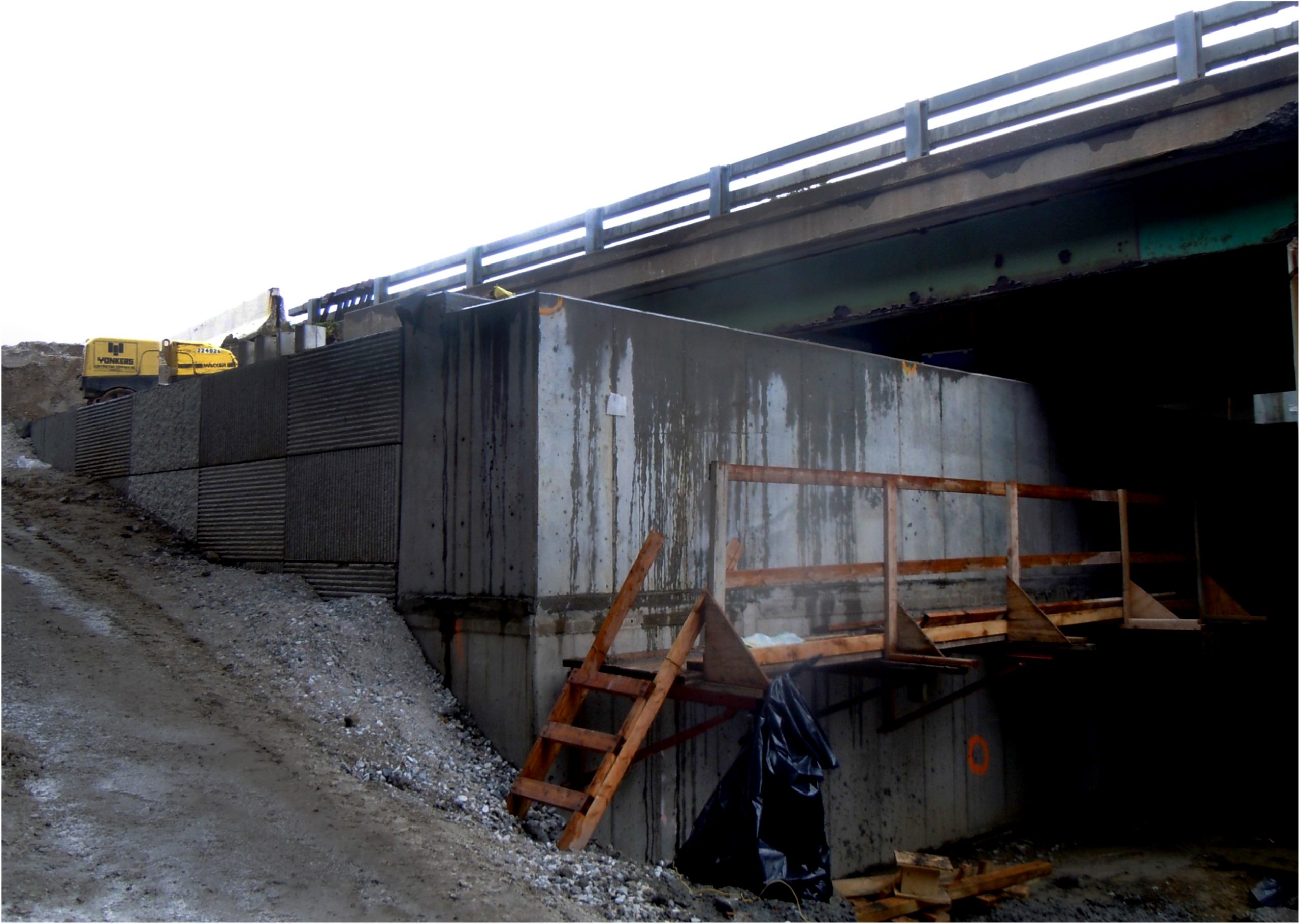
Each replacement bridge has three 12-ft-wide traffic lanes, a 6-ft-wide (left) shoulder, and a 12-ft-wide (right) shoulder with TL-5 concrete barriers. Each cross-section consists of six adjacent 36-inch-deep NEXT D beams with 6-inch-wide UHPC closure joints. The semi-integral abutments consist of elevated cast-in-place concrete straddle-bent cap beams supported on 6-ft-diameter rock-socketed drilled shaft foundations. Precast elements include NEXT D beams, 4-ft-wide end diaphragms cast monolithically with four slide shoes, wingwalls, approach slabs slid with the spans, and sleeper slabs.
The 15 percent grade of the existing bridge and the significantly wider replacement bridge created a challenge in maintaining the design requirements for minimum under-clearance. NEXT D beams minimized structure depth to address the under-clearance issue, were cost effective, and expedited design and construction. The NEXT beams were fabricated with 5-inch rebar extensions along their length; the outside NEXT beams were fabricated with barrier rebar extending from the deck.
The new bridges are approximately two feet higher in elevation than the existing bridges to provide adequate under-clearance. Both bridges are jointless, with expansion joints provided only at the ends of the approach slabs. The approach slabs were designed for both dead load and live load to act as jump spans until the controlled low-strength material fill was placed behind the abutments. All details for the NEXT beam superstructure, precast approach slabs, and UHPC closure joints were developed according to the standard ABC concepts in the SHRP2 R04 Toolkit.
Construction Method:
Existing approach roadways were widened into the median to accommodate the additional lane in each direction. Significant earthwork was needed to achieve the desired profiles due to the elevation difference between eastbound and westbound roadways. The contractor also used the median for access and work areas.
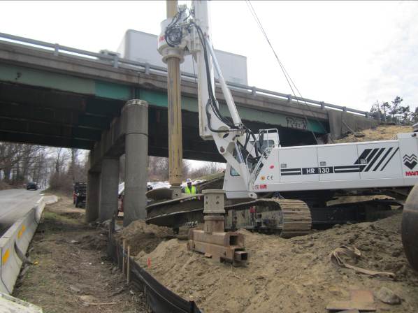
Abutment drilled shafts were constructed on either side of the existing bridge outside the existing bridge footprint due to the limited under-clearance available to the drilling rigs. The cast-in-place concrete straddle-bent abutments were then constructed under the existing bridge with limited excavation. This work was done prior to closure, without disrupting traffic.
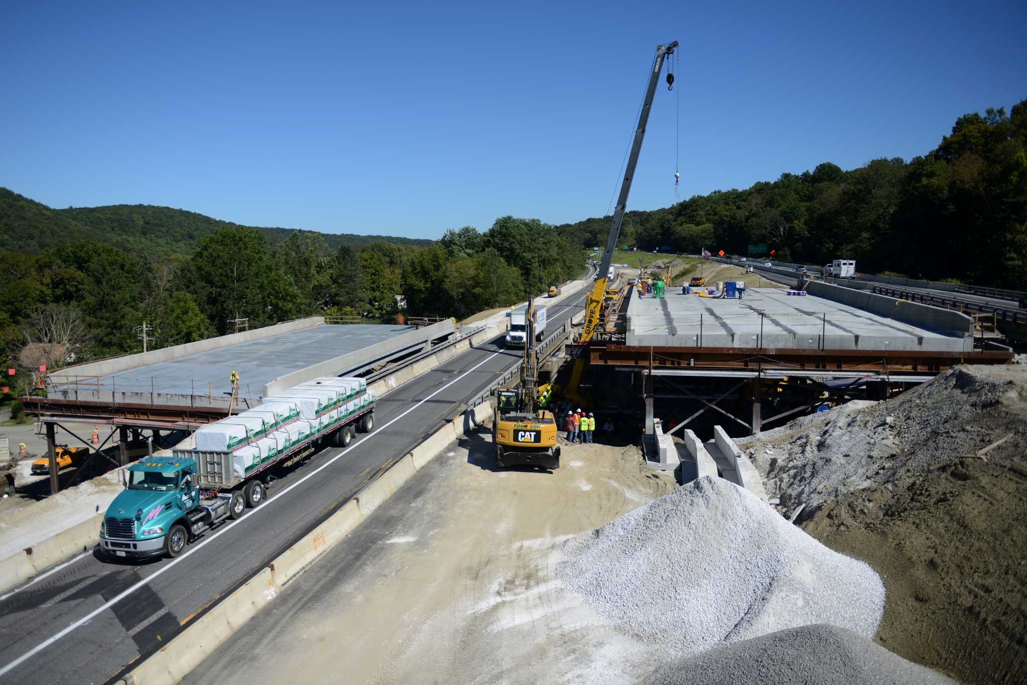
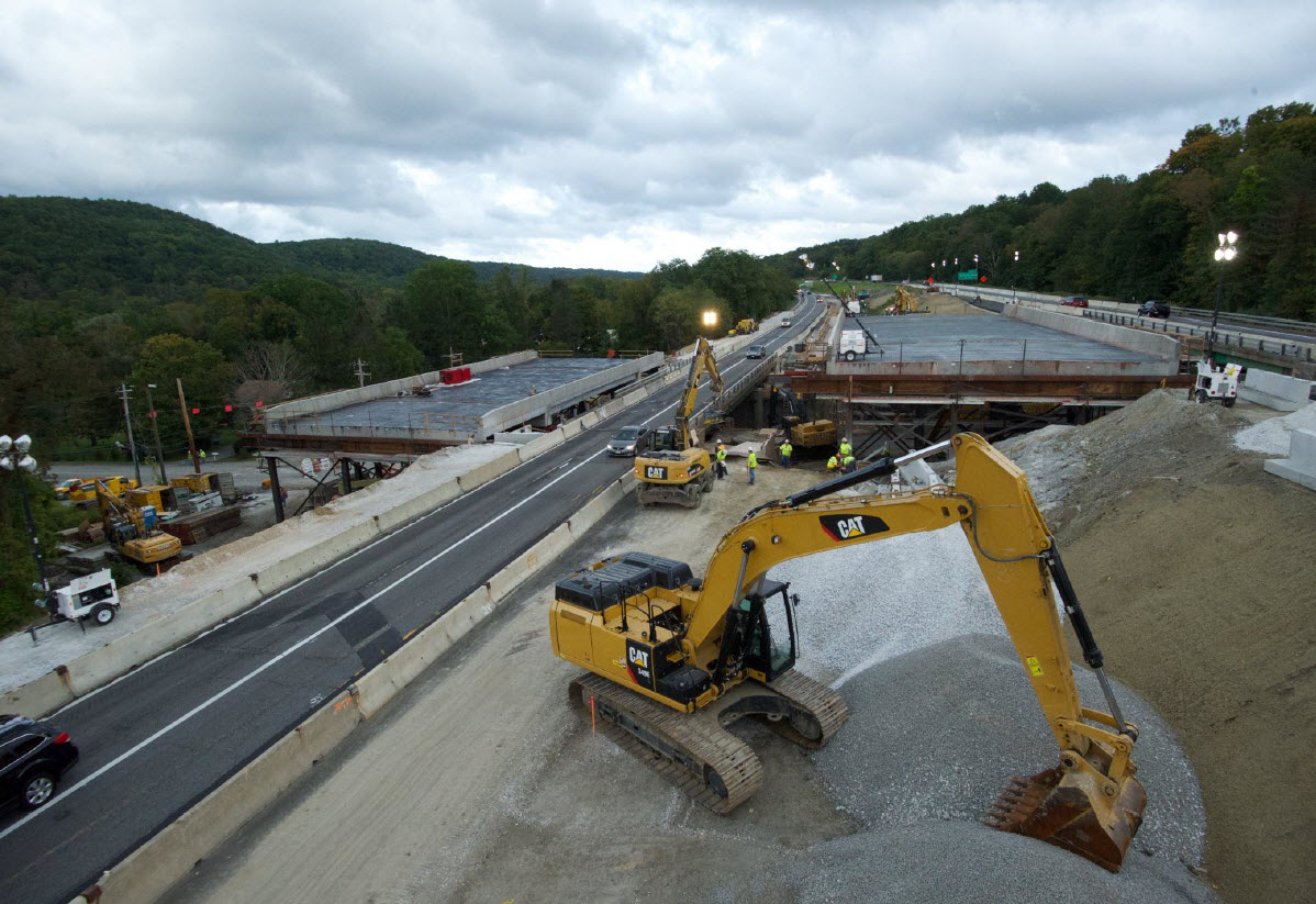
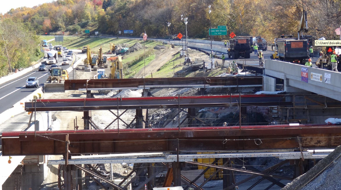
Temporary falsework to support the new spans was built adjacent to and in line with the new abutments. Secondary falsework was built adjacent to the new sleeper slab locations. The new spans and approach slabs were constructed on the temporary falsework concurrently with substructure construction.
The precast end diaphragms with slide shoes, the NEXT beams, and the approach slabs were delivered to the job site just prior to installation. The end diaphragms were erected over the slide tracks on the falsework. The reinforced elastomeric bearing pads were then placed on the end diaphragms, and the NEXT beams were erected on the pads. The approach slabs were erected, supported on the end diaphragm at one end and on the secondary falsework at the other end. After the approach slabs were erected, the end diaphragms, NEXT beams, and approach slabs were made integral with UHPC closure pours. The concrete barriers were slip formed after the longitudinal closure joints were cast.
After the initial substructure work was completed and the superstructure was constructed, traffic was detoured. The existing bridge was demolished using conventional methods, the approach roadway was raised to the new profile, and the precast sleeper slabs were placed at the end of each approach to serve as sliding surfaces for the approach slabs.
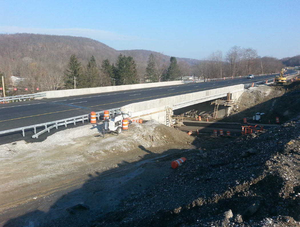
Prior to each slide, the contractor performed a trial slide to ensure the proper functionality of the slide systems. Deck surfaces were sprayed with a three-coat waterproofing system. The superstructure and approach slabs were then slid in place on polytetrafluoroethylene (PTFE) pads on the stainless steel tracks using hydraulic jacks that pushed the structure in 1-ft increments. An asphalt overlay was then placed over the length of the structure. The approach roadways were raised approximately two feet to meet the new bridge elevation. Traffic was then rerouted onto the new bridge.
Timeline:
- A pre-bid meeting was conducted in July 2012. NYSDOT and SHRP2 R04 representatives made presentations on the innovative design aspects of the bridge and answered contractor questions.
- Bid opening was in November 2012.
- The contract was awarded in December 2012.
- The preconstruction meeting was held in January 2013.
- Construction began in March 2013.
- The first lateral slide occurred in September 2013, nine months after the award of the contract and less than six months after the start of on-site bridge construction activities. The second slide occurred 1 month later, in October 2013.
The contract included an incentive/disincentive clause to award or penalize the contractor $10,000 per hour for early or late completion, respectively, to ensure I-84 was opened to two-way traffic by the following business day ($50,000 max incentive). The existing bridges were to be closed at 5 p.m. on Saturdays, and the new bridges were to be opened by 1 p.m. on Sunday. Each slide was completed in 18 hours, within the allowed 20-hour window. The two replacements would have required two years using conventional construction.
Stakeholder Feedback:
- Construction duration was significantly reduced, from two construction seasons to two weekends.
- Safety within the work zone was improved.
- Reduced Costs: $2.0M saved, primarily by not building a temporary bridge in the median.
- Impacts to the New York City watershed were substantially reduced; at least 5 acres of land did not have to be disturbed using ABC.
High Performance Material:
UHPC closure joints in all field connections in the superstructure and approaches
Project Planning
Decision Making Tools:Site Procurement:
Project Delivery: design-bid-build
Contracting: incentive / disincentive clause, value engineering
Geotechnical Solutions
Foundations & Walls: CIP substructure under traffic (abutment drilled shafts constructed outside footprint of bridge)Rapid Embankment:
Structural Solutions
Prefabricated Bridge Elements: MDcBc (Type D NEXT beams), precast wingwallPrefabricated Bridge Systems: FDcBc (Full-width concrete-Decked concrete Beam unit - Type D NEXT beams)
Miscellaneous Prefabricated: precast diaphragm, precast approach slab, other miscellaneous prefabricated element – precast sleeper slab, UHPC closure joint, asphalt overlay w/membrane
Costs & Funding
Costs:There were 10 fully responsive bidders. The awarded bid was $10.243 million, within 3% of the $10.536 million engineer’s estimate. It included several items, e.g., approach roadway work, that were not part of the ABC project itself.
The ABC process saved NYSDOT $2 million by eliminating the need for a temporary bridge.
The innovative technology resulted in savings of $0.9 million in construction costs and $1.37 million in user delay costs. Together, the savings represent 22 percent of the project construction cost.
Funding Source:
Federal and State
Incentive Program:
- HfL [Highways for LIFE]: $2.0 million
- SHRP2 [Strategic Highway Research Program 2]: $300,000
- SHRP2 R04 funding support for ABC upcharge: $250,000
- ARRA [American Recovery and Reinvestment Act]
Additional Information
Downloadable Resources
Contract Plans: View D262100_Plans_Volume_1of1_pp1-101.pdf
View D262100_Plans_Volume_1of1_pp102-183.pdf
View D262100_Proposal_Book_1of3.pdf
View D262100_Proposal_Book_2of3.pdf
View D262100_Proposal_Book_3of3.pdf
View D262100-Bid-Tab-Spread-Report.pdf
Other Related Information:
Other Related URLs:
Go to:
https://abc-utc.fiu.edu/resources/shrp2-implementation/
Go to:
http://www.trb.org/Main/Blurbs/168046.aspx
Go to:
http://onlinepubs.trb.org/onlinepubs/shrp2/SHRP2_R04LateralSlideAddendum.pdf
Go to:
https://abc-utc.fiu.edu/mc-events/new-york-states-i-84dingle-ridge-road-lateral-bridge-slide/?mc_id=54
Go to:
https://americastransportationawards.org/ny-i-84-bridges-over-dingle-ridge-road-replacement-project/
Go to:
https://www.youtube.com/watch?v=3sVQvCqHPbQ
Go to:
http://www.peckham.com/project/nysdot-rapid-bridge-construction-i-84-over-dingle-ridge-rd-putnam-county-ny/
NYSDOT, SHRP2
Contacts
Wahid Albert, P.E.
Chief Engineer
NYDOT
Wahid.Albert@dot.ny.gov
518-457-4422
Submitter:
Jennifer Smoker
SHRP2 Consultant
Jacobs Jennifer.Smoker@jacobs.com
202-494-2076
Designer:
HNTB New York Engineering and Architecture, P.C.
Bala Sivakumar
P.E.
Fab1:
Dailey Precast, LLC, Shaftsbury, VT
precast elements
Company Rep.
Precast Concrete Engineer/Fabricator
Sup1:
Marino Crane
lateral slide
Company Rep.
Heavy Lift Supplier
Sup2:
Parsons Brinkerhoff
construction inspection Company Rep.
Sup3:
Peckham Materials Corp.
asphalt overlay Company Rep.
Contractor:
Company Rep.
General Contractor
Yonkers Contracting Co.
Subcon1:
HVEA Engineers Contractor’s Consulting Engineer Company Rep.
Subcon2:
Siefert Associates, LLC Contractor’s Erection Engineer Company Rep.