
State: VT
County:
Owner: State
Location: Urban
Spans: One-span
Beam material: Concrete
Max Span Length (ft.): 119.81
Total Bridge Length (ft.): 119.81
Construction Equipment Category: Other ABC Method
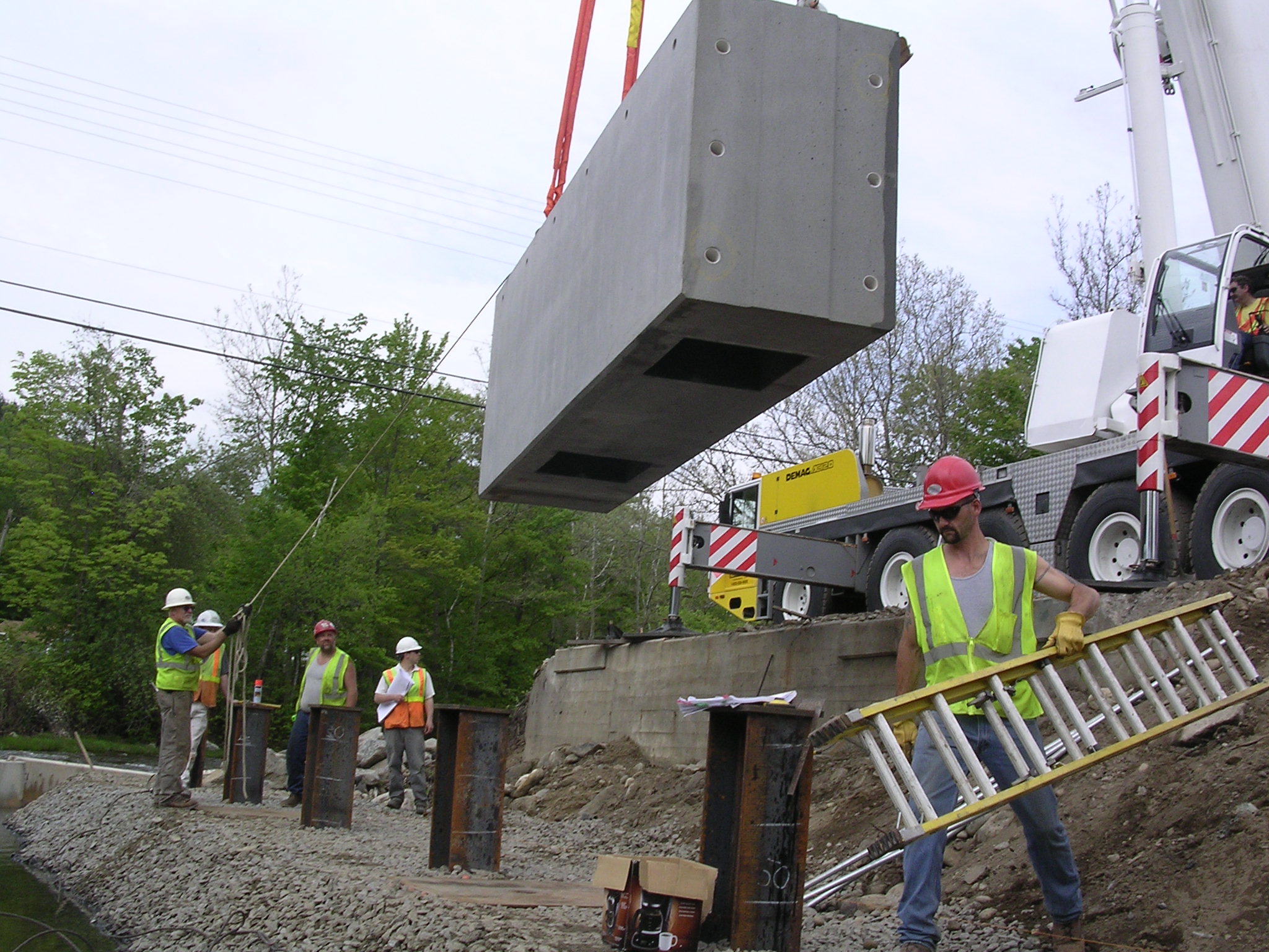
ABC Construction Equipment: high-capacity crane(s)
State ID Number: BRF 025-1(37)
NBI Number: 2E+14
Coordinates
Latitude: 43.2580566 | Longitude: -72.5877762


Bridge Description
Project Summary:precast abutment caps and precast wingwalls
Project Location:
Vermont Route 103 (rural principal arterial) at its intersection with VT Route 11, over the Middle Branch of the Williams River in the town of Chester in Windsor County
Impact Category:
Tier 5 (within 3 months)
Mobility Impact Time:
ABC: 8 weeks; Conventional: 6-month closure in two construction seasons
Primary Drivers:
reduced traffic impacts, reduced onsite construction time, improved work-zone safety, minimized environmental impacts
Dimensions:
119.81-ft long and 41.17-ft wide single-span curved steel plate girder bridge; 65º skew
Average Daily Traffic (at time of construction):
7200
Traffic Management (if constructed conventionally):
If constructed conventionally, extended use of 9-mile detour.
Existing Bridge Description:
The existing two-span continuous rolled steel beam bridge was 111-ft long and 32-ft wide with cantilevered concrete abutments founded on spread footings. It had two 10.75-ft-wide traffic lanes and a 3.5-ft-wide sidewalk. Built in 1935, the bridge was deteriorated and required replacement.
Replacement or New Bridge:
The Vermont Agency of Transportation (VTrans) reviewed the various construction options to limit traffic disruption during the replacement of Bridge 9 and a second bridge on VT Route 103, Bridge 8. The solution was to combine the two bridge replacements into one contract, detour traffic and close both bridges, use prefabrication to limit the closure time, specify incentives / disincentives in the contract to ensure the closure times were achieved, and do extensive public outreach prior to construction to inform the public of the impending closures. The Bridge 9 details are described here; see “Chester VT 103 Bridge 8” for details on the other bridge replacement in the project.
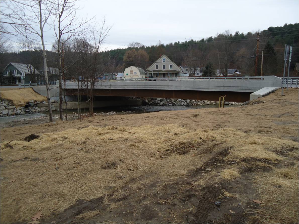
The replacement bridge has two 11-ft-wide traffic lanes, a 6-ft-wide shoulder and 5.5-ft-wide raised sidewalk on one side, and a 6-ft-wide shoulder on the other side. The cross-section consists of seven 46-inch-deep curved steel plate girders spaced at 6 ft with an 8-inch-thick cast-in-place concrete deck. The cast-in-place concrete deck was allowed as a Value Engineering proposal instead of the 8-inch-thick precast concrete deck shown in the contract plans. The 56.11-ft-long precast integral Abutment 1 and 62.17-ft-long precast Abutment 2 were each fabricated in three segments to reduce weight. The precast wingwalls had total lengths of 46 ft and 16 ft and varied in height from 6 ft to approximately 13 ft. The wing wall and footing thickness was 10 inches, and the footing was designed with a heel only and no toe. Prefabricated elements also included precast approach slabs.
Construction Method:
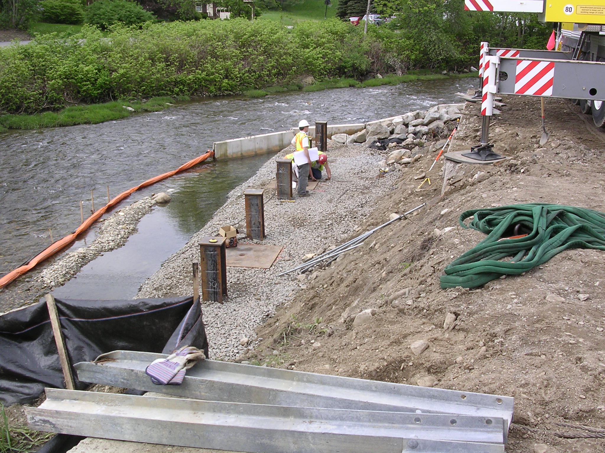
Precast elements were fabricated with high-performance concrete (HPC) at a precast plant and shipped to the site. The 4-ft-wide precast abutment cap segments were fabricated with 2.33-ft x 2.50-ft pockets extending into the caps 3.33 ft from the bottom surface and 6-inch-diameter ducts extending from the top of the pockets to the cap surface. The connecting ends of the abutment segments were keyed and match cast.
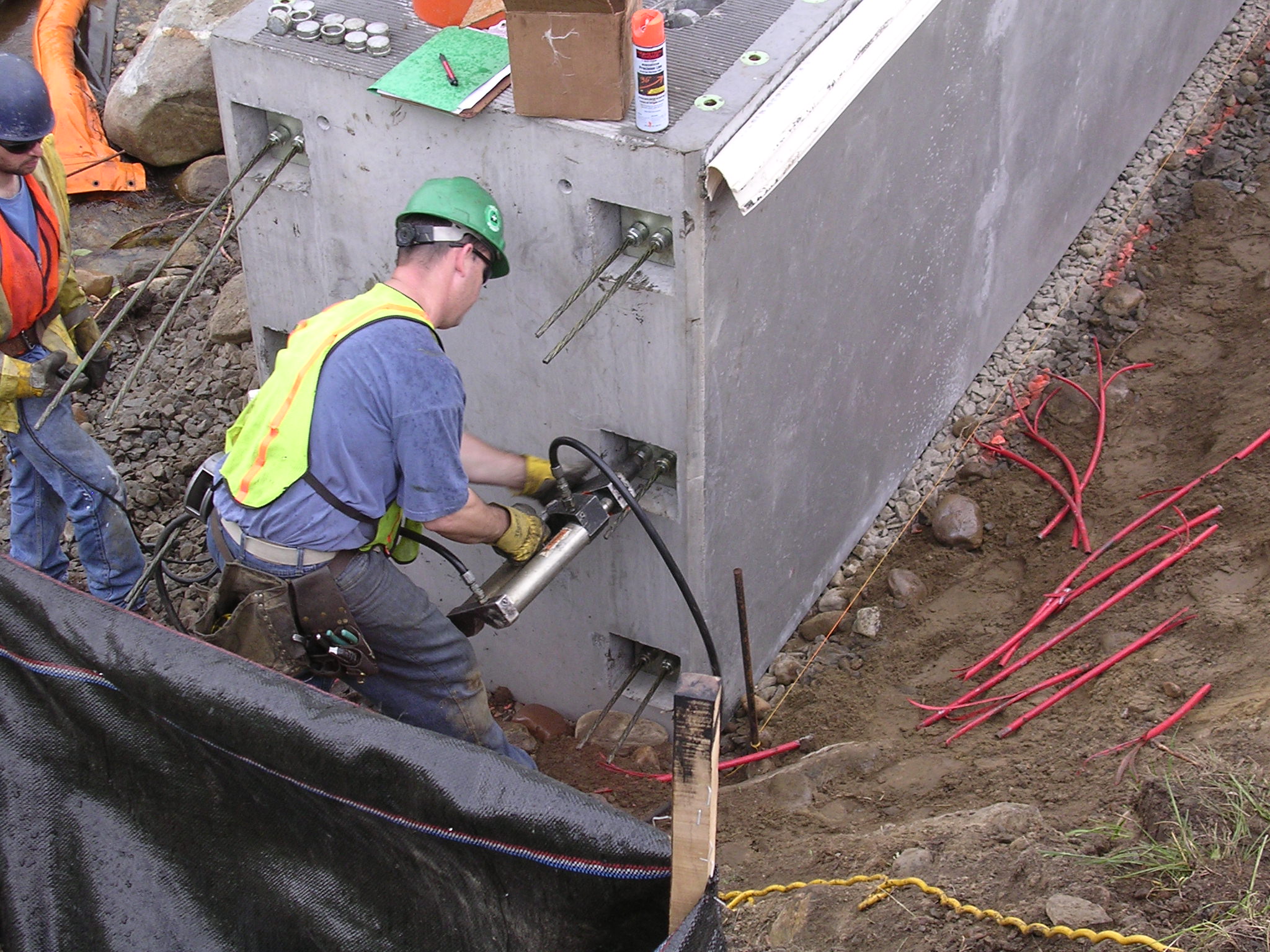
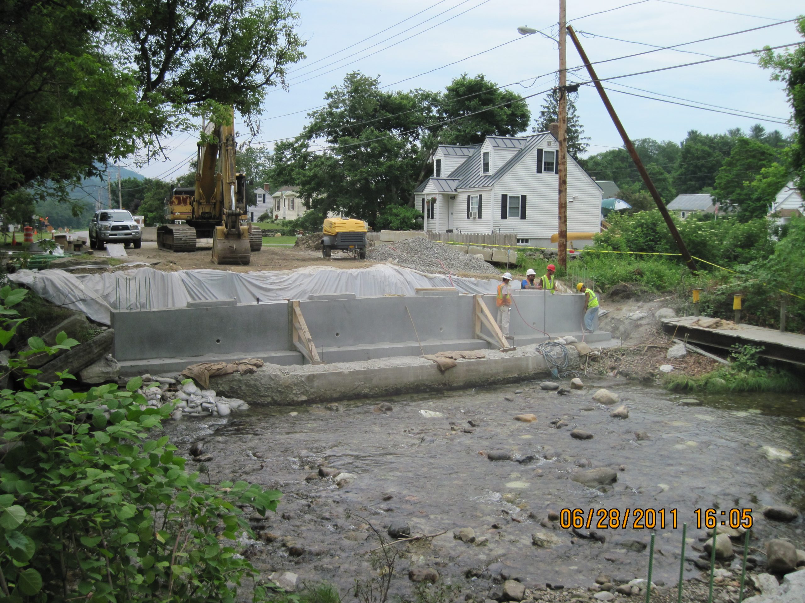
The contractor detoured traffic and closed the bridge. The contractor graded the foundation to the required elevation and drove the steel H-piles. The abutment cap segments were erected over the piles, with piles embedded 3 ft minimum. The vertical match-cast key between segments was coated with a thin layer of epoxy bonding compound and the post-tensioning strands were installed in the ducts connecting the caps and tensioned; the ducts were not grouted. The cap pockets were then filled with self-consolidating concrete. Precast wingwall segments were erected to retain the roadway fill on opposite corners of the bridge, and backfill was placed.
The contractor erected the beams onto sole plates on the abutment caps and bolted them in place. Beam profiles were taken to determine the final finish grade. Shear studs were welded to the tops of beams and a cast-in-place HPC deck was placed. The cast-in-place concrete extended down onto the abutment cap to create a backwall and function as an integral abutment. The grade at the ends of the bridge was prepared, and the precast approach slabs were erected. Sheet membrane waterproofing and a 1.25-inch-thick asphalt overlay were placed. Longitudinal temporary barrier was placed to allow the bridge to be opened to two-way traffic. After the bridge was opened to traffic the sidewalk and aesthetic traffic railing were cast. Then the temporary barrier was removed and the final lift of 1.25-inch-thick asphalt overlay was placed.
The contract required that Bridge 9 be closed a maximum of 9 weeks, from 7 am on Monday, May 16 to 11:59 pm on Sunday, July 17. The contractor was allowed to work 24 hours a day, 7 days a week, including holidays, except that no work that created a noise level exceeding 75 decibels was allowed between the hours of 9 pm and 6 am.
The contract included a lump sum incentive of $60,000 if completed within 9 weeks. In addition, the contract included an incentive of $640 per hour that the bridge was opened to two-way traffic in less than 9 weeks. The maximum incentive was $200,000. The contract included a disincentive of $640 per hour that the bridge remained closed after 9 weeks, with no maximum disincentive. The contractor opened the bridge in 8 weeks and received the maximum incentive payment of $200,000.
Stakeholder Feedback:
See “Project Lessons Learned” document under “Other Related Information.”
High Performance Material:
- High-performance concrete (HPC) in CIP deck and precast substructure
- Self-consolidating concrete (SCC) in abutment cap pockets
Project Planning
Decision Making Tools: State processSite Procurement:
Project Delivery: design-bid-build
Contracting: full lane closure, incentive / disincentive clauses, lump sum bonus
Geotechnical Solutions
Foundations & Walls:Rapid Embankment:
Structural Solutions
Prefabricated Bridge Elements: precast abutment caps, precast wingwallsPrefabricated Bridge Systems:
Miscellaneous Prefabricated: match cast closure joints (abutments), PT ducts/un-bonded (abutments), socket connections (abutments), epoxy joints (abutments), asphalt overlay w/membrane, precast approach slabs
Costs & Funding
Costs:The engineer’s estimate for the project was $4.93 million for the two bridges. The low bid was $2.84 million. There were four bidders. The cost per square foot of bridge (including all construction engineering charges) was $440 compared to $550 for conventional construction in this region in 2011.
Funding Source:
Federal and State
Incentive Program:
Additional Information
Downloadable Resources
Contract Plans: View Chester-VT103-Bridge-9-ABC-except-VE-change-to-CIP-deck.pdf
View Chester-ProjectSpecialProvisions.pdf
Construction Schedule:
Other Related Information:
Other Related URLs:
Vermont Agency of Transportation
Contacts
Kristin M. Higgins, P.E.
State Bridge Engineer
Vermont Agency of Transportation
kristin.higgins@vermont.gov
802-498-3398
Submitter:
Mary Lou Ralls P.E.
Principal
Ralls Newman, LLC
ralls-newman@sbcglobal.net
512-422-9080