
State: NJ
County:
Owner: State
Location: Urban
Spans: Two-span
Beam material: Steel
Max Span Length (ft.): 59
Total Bridge Length (ft.): 118
Construction Equipment Category: Conventional
ABC Construction Equipment: Conventional
State ID Number: 1303156
NBI Number: 1303156
Coordinates
Latitude: 40.3180542 | Longitude: -74.3058319


Bridge Description
Project Summary:Project Location:
Gordon’s Corner Road over US Route 9 near the township of Manalapan in Monmouth County
Impact Category:
Tier 2 (within 3 days)
Mobility Impact Time:
ABC: 2 weekend closures ; Conventional: 10-month closure
Primary Drivers:
• reduced traffic impacts
• reduced onsite construction time
• improved work-zone safety
• improved site constructability – various overhead utility lines impact constructability
• improved material quality and product durability
• reduced life-cycle cost
Dimensions:
Average Daily Traffic (at time of construction):
64300
Traffic Management (if constructed conventionally):
Traffic management alternative, if constructed conventionally: extended use of 8-mile detour
Existing Bridge Description:
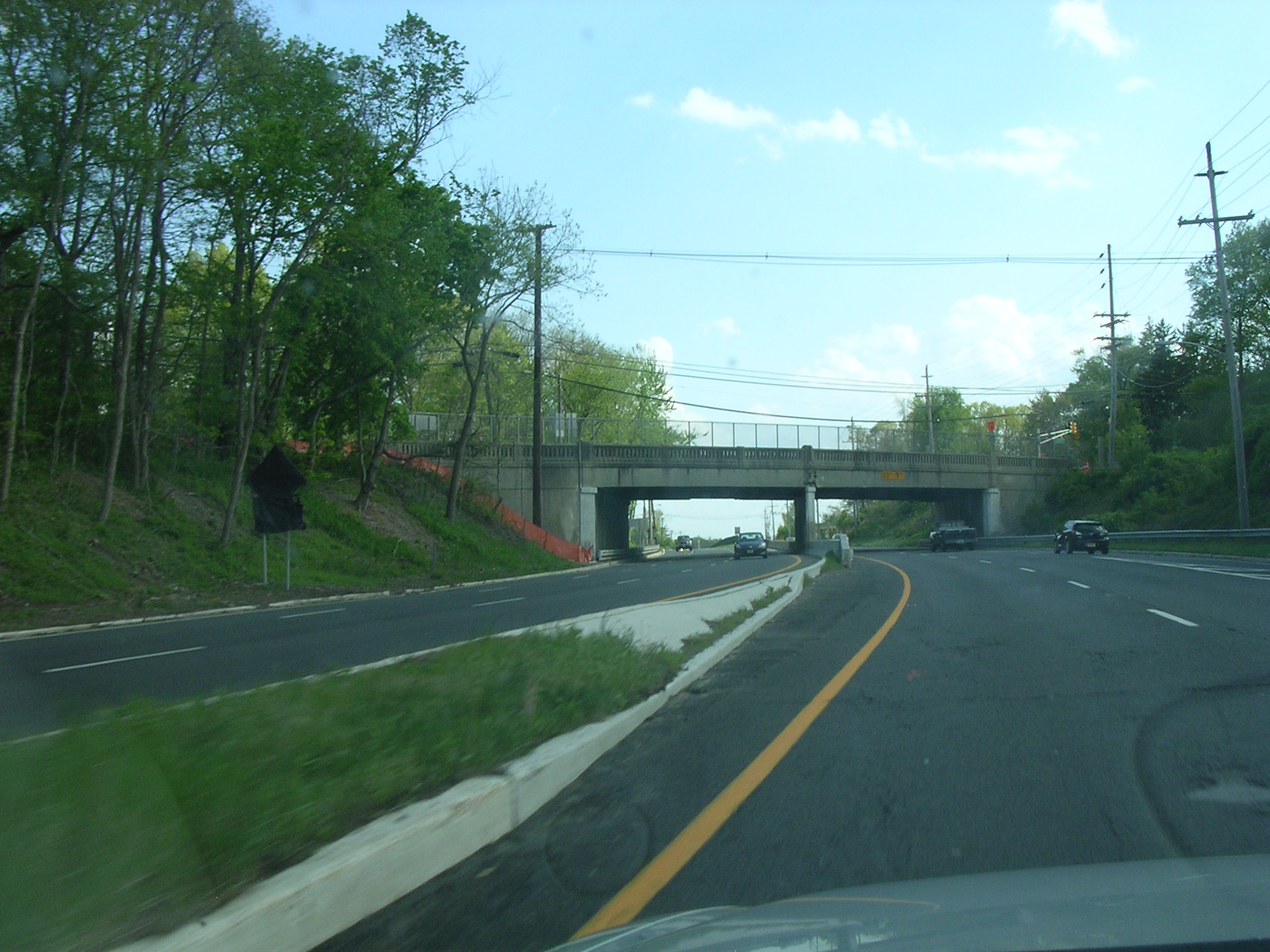
The existing two-span concrete-encased steel girder bridge had a 24-ft-wide traffic lane and no shoulders eastbound and two 12-ft-wide traffic lanes and no shoulders westbound. Its substructure consists of concrete abutments and interior pier on shallow foundations. Built in 1939, the bridge had insufficient vertical under-clearance and was damaged repeatedly by over-height loads. The superstructure required replacement.
Replacement or New Bridge:
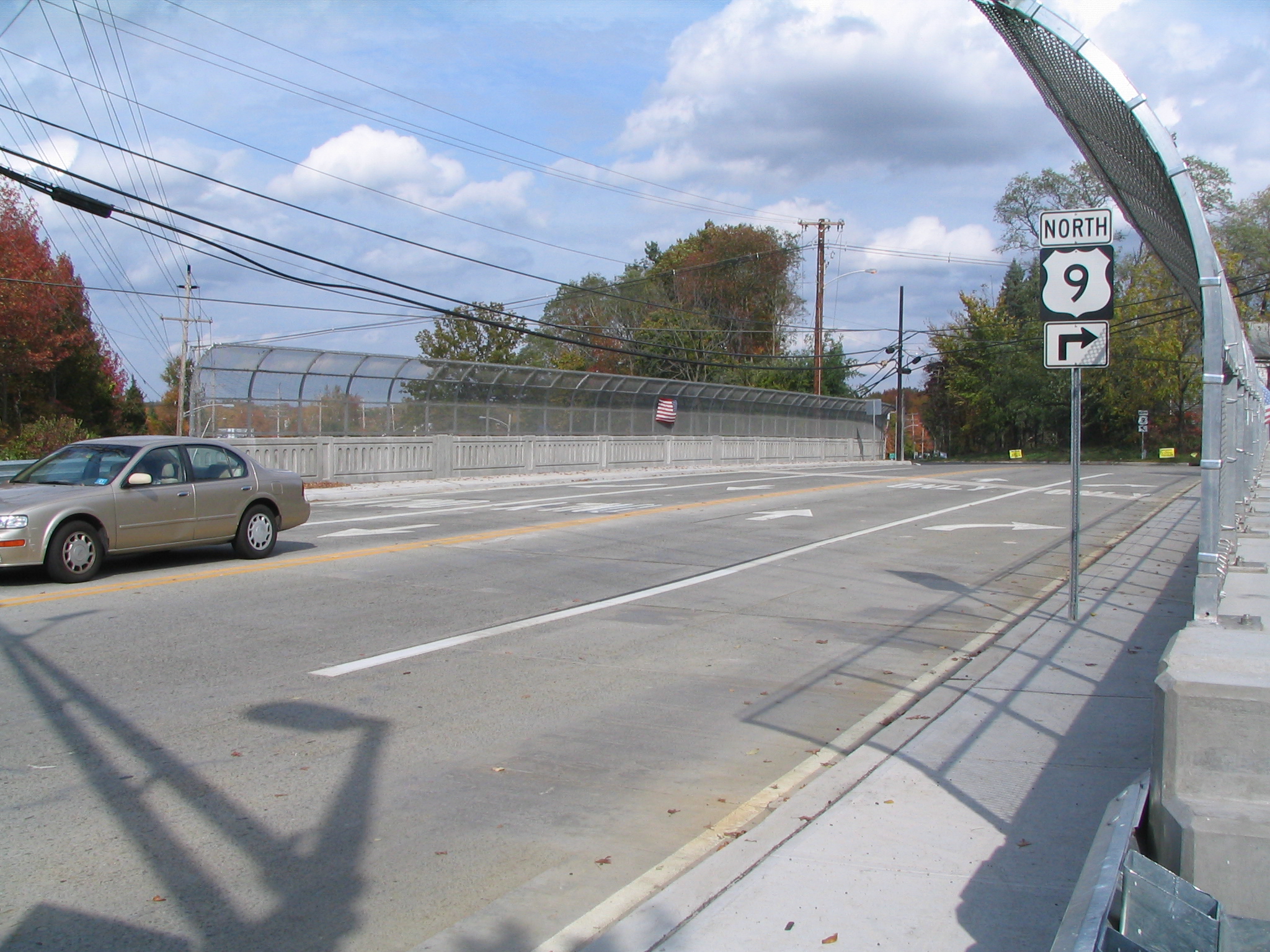
The replacement superstructure has a 14-ft-wide eastbound traffic lane, two 12-ft-wide westbound traffic lanes, a 12-ft wide shoulder, a 2-ft-wide shoulder, and two 5.75-ft-wide sidewalks. The cross-section consists of five 9.33-ft-wide interior modular decked beam units and two 9.67-ft-wide outside modular decked beam units. Each modular decked beam unit consists of two W24x131 steel girders with 8.5-inch-thick concrete deck. Other prefabricated elements included precast cheek walls and precast approach slabs.
Construction Method:
Construction Methods – As Designed:
The intent of the contract was to replace the superstructure and approach roadway during a one-weekend closure of Gordon’s Corner Road with concurrent lane restrictions on Route 9, and to perform other work using lane restrictions on Route 9 and Gordon’s Corner Road. Route 9 had two lanes and an acceleration/deceleration lane in both northbound (NB) and Southbound (SB) directions. Gordon’s Corner Road was striped for two westbound (WB) lanes and one eastbound (EB) lane. The contract plans provided details for existing superstructure removal and new superstructure installation using self-propelled modular transporters (SPMTs). The contract did not specify the use of the SPMTs but instead included tight timeframes and high disincentives if the timeframes were not achieved. However, the project special provisions specifically advised contractors that the project design had been developed assuming the use of SPMT units for removal and erection activities.
The as-designed approach to the project was to:
1. Construct temporary crossovers in the median of Route 9 no more than 30 days before the weekend replacement. Once completed the crossovers were closed pending the weekend construction.
2. Beginning two weeks before the weekend replacement, all substructure repairs to the pier and abutments would be performed and temporary shielding installed using nighttime lane closures on Route 9.
3. Beginning two weeks before the weekend replacement, Gordon’s Corner Road would be restricted to one lane in each direction and partial demolition of the bridge would commence. This included removal of the balustrades, partial removal of the headers at the pier and abutments, cutting and removing all four wingwalls down to the top of seat elevation, partial removal of the concrete approach road and subgrade preparation for placement of precast approach slabs.
4. One week before the weekend replacement, redundant ramps would be closed and staging area preparation would begin. The ramps could remain closed for one week after the weekend replacement for demolition of the existing superstructure.
5. At 6 am on Friday of the weekend replacement, the commuter parking lot adjacent to the site would be closed and SPMT units would be assembled and calibrated.
6. At 8 pm on Friday, Gordon’s Corner Road would be closed and final demolition would begin. The approach roadway would be removed and precast slabs placed throughout the weekend period.
7. At 10 pm on Friday, Route 9 would be restricted to one lane in each direction and traffic would be shifted first to the NB side using the preconstructed crossovers. SPMTs would remove the existing west span superstructure and transport it to the staging areas east of Route 9. They would then be loaded with the superstructure panels and set the new west span. This portion of the project would require four short-term traffic stoppages on Route 9 while the SPMTs crossed from the west span to the staging on the east side. This was considered acceptable as all moves would occur late at night or very early on Saturday morning when little traffic was expected. Except for these four stoppages, it was expected that traffic on Route 9 would be able to flow freely through the site.
8. Once the west span was in place, Route 9 traffic would be shifted to the SB side and the east span would be removed and new panels erected using the SPMTs. This work would occur on the side where the staging areas were located so no disruption of Route 9 traffic was anticipated.
9. Route 9 and Gordon’s Corner Road would be reopened by 5 am Monday morning. The parking lot would also be reopened for commuter use. Certain ramps could remain closed for an additional seven days to allow for offline demolition of the existing superstructure.
Construction Methods – Actual Methods Used by Contractor:
The contractor constructed the crossovers and completed the substructure repairs according to the recommended staging.
Subsequently, the contractor did not follow the recommended staging and did not perform any pre-demolition work on the bridge prior to the weekend replacement. They did not remove the balustrades or begin demolition of the headers. They elected not to pre-demolish the existing wingwalls; this had serious consequences during the weekend construction. The contractor did work up an installation procedure with the approach slab supplier where installation of the slabs could begin in advance of the weekend construction, saving time on this operation.
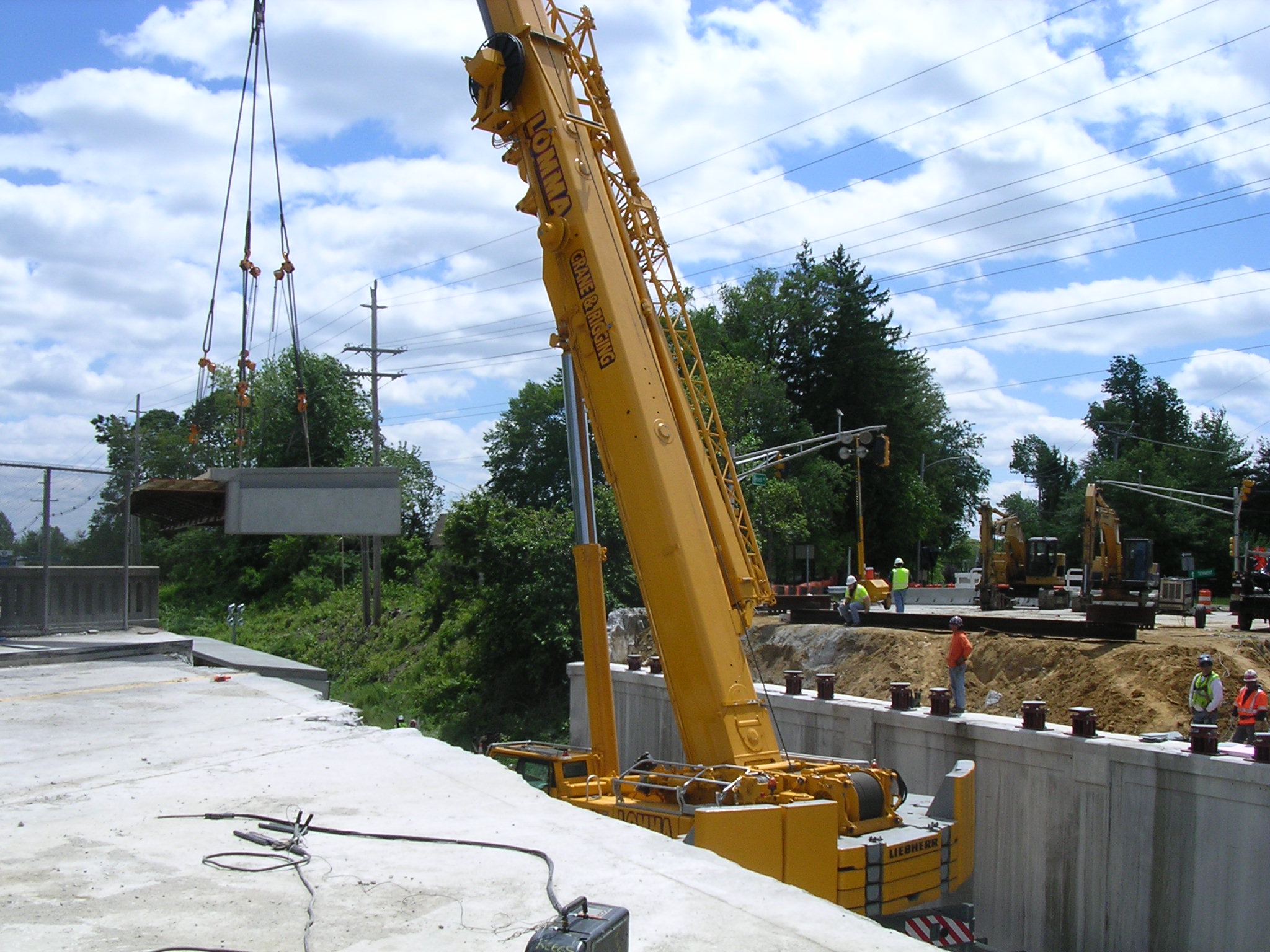
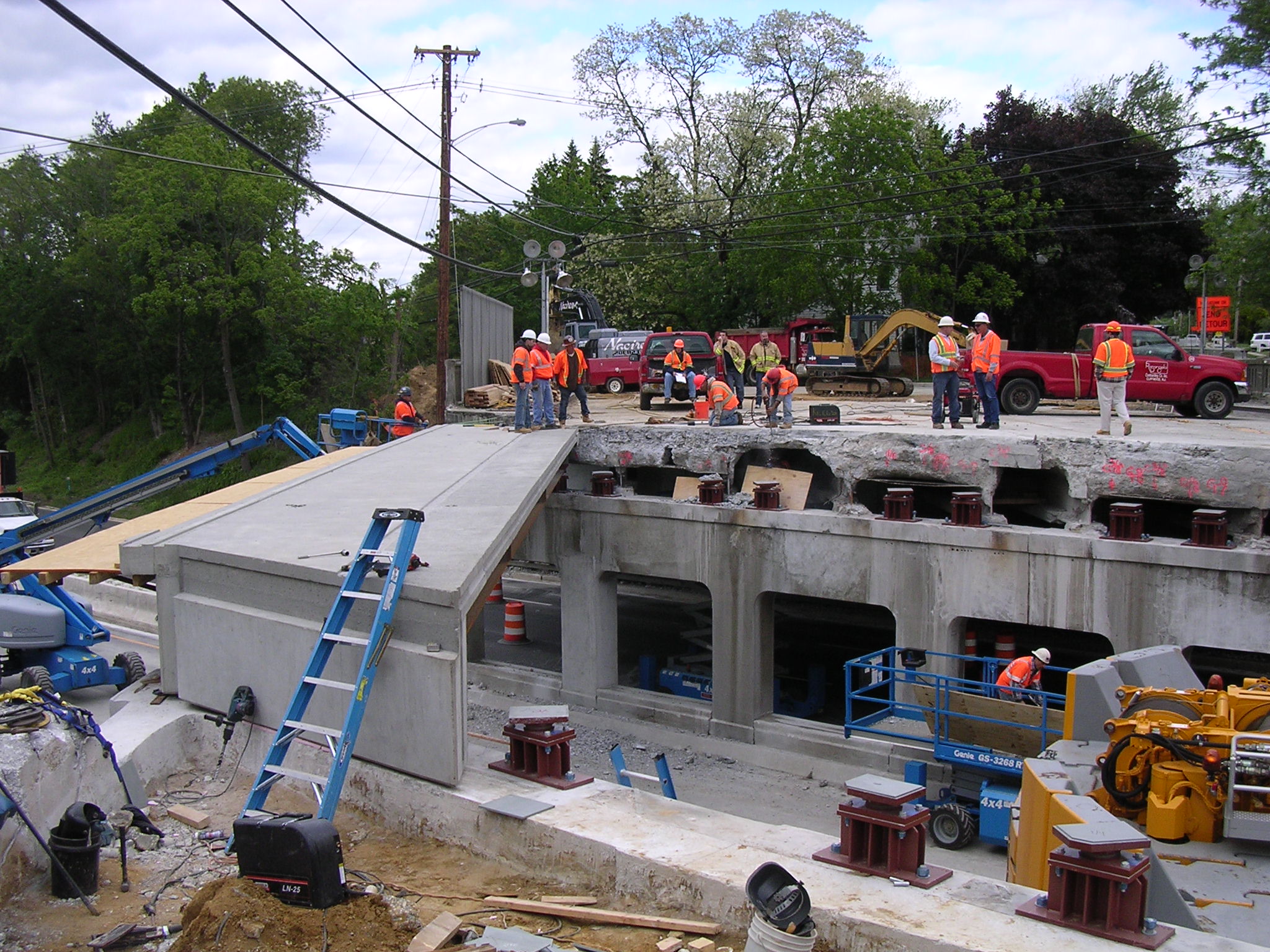
Work began according to schedule on the west span. The contractor chose not to use SPMTs. The existing spans were demolished using conventional methods. The limited work space at the bridge site restricted the amount of demolition equipment that could be staged for the conventional removal of the existing superstructure. The concrete deck and encasement was removed with hydraulic rams and shears mounted on excavators with the debris being dropped into dumpsters placed on the roadway below. Beams were then removed piece by piece using a crane. Each pick required temporarily stopping traffic on Route 9. Stoppages for removal operations alone greatly exceeded the four stoppages which would have been required if SPMTs were used. Beams were picked and placed on flatbed tractor trailers for removal from the site. During removal one trailer suffered a tire blowout which blocked access and shut down operations for over an hour until it could be offloaded and removed. This type of delay would not have occurred with SPMTs.
After the beams were removed, the contractor commenced cutting the wingwalls and abutments and drilling for the steel pedestal anchor bolts. The contractor elected to use only one crew to core for the anchors. Additionally, they did not have enough spare bits. Drilling took much longer than anticipated as four crews could have worked concurrently. Time was lost waiting for new core drill bits to be transported from the main yard. Only one crew was used to cut the wingwalls and abutments further slowing operations.
The steel bearing pedestals were then placed, and the modular decked beam units were erected. These were also erected conventionally using a crane. Due to restricted clearances, placement of the units was slow. The contractor also initially refused to use the erection system provided by the supplier which delayed installation. Eventually the system was used and production increased. As with the demolition, traffic on Route 9 was temporarily stopped during the erection pick for each unit. This compounded traffic disruption as it occurred during peak periods.
Precast approach slabs were placed and other finish work was completed. Only one span was completed during the first weekend. Construction operations were suspended and Route 9 was reopened to two lanes in each direction for the Monday morning rush hour. Because of the gap between the completed west span and the existing east span, traffic could not be restored on Gordon’s Corner Road and the bridge remained closed until the next weekend.
The following weekend the process was repeated for the second span replacement.
The contract required that a one-weekend replacement be done no later than early May 2010 and that all work required for interim completion be done over the weekend in 72 continuous hours beginning on a Friday at 6 am. The contract included an incentive of $10,000 per hour for opening to traffic prior to 6 pm on Sunday. The contract also included a similar disincentive of $10,000 per hour for late opening (after 5 am on Monday morning). Additional disincentives ranged from $1,500 to $2,900 per day for not achieving other time requirements such as ramp closures and lane closures for prep work.
In summary, the contractor chose to not use SPMTs, choosing instead to use typical construction equipment to remove the existing bridge conventionally and to install modular decked beam units. The conventional construction required two weekend closures rather than the required 72-hour one-weekend closure. The contractor was assessed $530,000 in disincentive charges.
Stakeholder Feedback:
A number of construction time-saving measures were designed into the bridge details:
• The headers were cast integrally with the modular decked beam units, eliminating a cast-in place pour.
• The headers were notched during fabrication to accept the precast approach slabs, with the expansion joints located off the new, jointless bridge at the interface between the first and second row of precast approach slabs.
• Steel pedestals were used to adjust for reduced structure depth (and thus increased under-clearance), and required only one round of drilling and grouting of bolts to attach them to the existing bridge seat. Utilizing steel pedestals eliminated a second round of drilling and grout cure time that would have been required for the typical rapid-set cast-in-place concrete or precast concrete pedestals which require two rounds of drilling and grouting, initially for the reinforcement to attach the pedestal to the existing seat and then to attach the bearing anchor bolts to the pedestal.
• In order to ease installation of the superstructure units, the headwalls and wingwalls were cut to the bridge seat elevation. This created a level surface which eliminated potential conflicts between the new superstructure and existing substructure when setting the units. This allowed the use of the existing, narrow center pier as the control when setting the units instead of being confined by the headwalls. As such all units would be aligned on the pier and adjustments made at the wider abutment bridge seats. Additionally, the removal of the existing headwall and portion of the wingwalls eliminated the potential for variation in elevation between the existing and new structure as the headwalls were cast integrally with the superstructure and the wingwalls would be reconstructed to meet the proposed grade.
• The modular decked beam units were constructed in a precast plant. To ensure proper fit-up in the field, the contractor’s surveyor was required to lay out a mock-up of the substructure on the ground at the plant. This mock-up was important because of the tight clearances, the bridge’s high skew, and the curved substructure elements which were originally constructed on the same radius at both abutments and the pier (not concentric). A template of the bridge seats at the abutments and pier were created and the units were erected on the template. This preliminary mock-up identified problems that could be addressed before the weekend work commenced, eliminating delays which would have occurred if the problems were first encountered during construction.
• Disc type bearings were chosen to accommodate anticipated construction tolerances and provided additional flexibility with the existing substructure geometry, in which variable (high) skews were required to accommodate the curved substructure.
Other important design aspects included:
• Each SPMT supplier had different approaches to the project. One used false work which required a larger staging area. Another used straddle cranes to remove and place loads on the SPMTs. This required less staging area but had higher equipment costs. In order to provide an equitable bidding environment, two nonstandard pay items were created. One was for preparation and restoration of the staging areas and the other was for furnishing equipment for superstructure removal and erection. The expected result would be that the SPMT supplier using false work would have a higher cost for the staging area pay item and a lower cost for furnishing equipment while the supplier using straddle cranes would have a higher cost for furnishing equipment and a lower cost for staging area impacts.
• Electrochemical chloride extraction (ECE) was used to remediate salt contamination of the pier. This process was applied after the superstructure replacement. Using the ECE process allowed the project to advance as a $6 million superstructure replacement project rather than a $22 million bridge and interchange reconstruction which would have taken years to program and construct.
• Precast cheek walls were used to match the architecture of the original bridge.
• The entire bridge was sealed with a silane solution.
• The spans were made continuous for live load and to address seismic considerations by bolting connection plates to the stringers after erection. This eliminated the deck joint but did require a cast-in-place closure pour in the deck which was made with latex-modified concrete to speed curing. Reinforcement was installed at the closure joint utilizing cast-in threaded inserts and splicing over the bars to span the pier. This was the only cast-in-place pour planned during the entire replacement weekend. The modular decked beam units were attached transversely utilizing standard diaphragm details, the joints between the units and lifting holes were sealed utilizing high strength, rapid-set mortar.
• The bridge and approach slabs received a diamond grind finish without an overlay.
• The special provisions included equipment specifications for SPMT units which identified movement capabilities required, most importantly, crab and carousel movement capability.
Lessons learned:
• The plans and specifications were well developed. The contractor exerted considerable effort in the beginning of the project to change the recommended staging to obtain an extension in time to complete the work over more than one weekend. Ultimately, the contractor’s attempts were unsuccessful because the contract documents anticipated many different conditions, and the project was designed to address “what if” scenarios. For example, the steel pedestals were designed assuming up to 60 percent of the underlying seat concrete was in poor condition. This was the result of a close working relationship between the consultant designer and the NJDOT project manager and subject matter experts. There were numerous, long working meetings where every imaginable situation was discussed and solutions developed.
• The FHWA specifications used as guidance during design development worked as intended. The contractor only filed one claim for plan errors for approximately $5,000 which was dismissed because the error was the result of the contractor not coordinating the work of the fabricators. In the end, the contractor was not able to identify anything in the contract documents which supported an extension in contract time and they were assessed $530,000 in disincentive charges.
• All of the recommended staging and design details prepared to accelerate construction were acceptable and served to reduce the delays which actually occurred. While there were significant delays in drilling for the steel pedestals, the delays would have been compounded if cast-in-place pedestals were specified as many more holes would have been required for reinforcement and a second round of drilling would have been required for the anchor bolts. Delays were encountered because the contractor did not cut the wingwalls and abutments until the weekend but if the existing concrete had not been removed, installation of the superstructure units would have taken even longer. Had many of these details not been included, the project could have extended over more than two weekends.
• The precast approach slabs worked as intended. When the project was initially designed, it was expected that the slabs would have to be installed from the bridge out to the limits of work. This was originally thought to be the critical path work for the project assuming SPMTs were used. The fabricator was able to develop an installation system where the slabs could be installed from the limits of work in towards the bridge. This allowed many of the sections to be set before the weekend superstructure replacement. Only the two rows nearest the bridge remained to be set during the weekend. The second row of approach slabs was formed slightly oversized and then cut in the field to fit.
• Incorporating the headers into the superstructure units and casting them to provide a seat for the precast approach slabs worked as intended saving significant time during construction.
• Eliminating the joints on the bridge by moving the expansion joint into the approach slabs worked well.
• The ECE process performed as expected and chloride contamination was virtually eliminated. Any chloride that remained was well below levels required to initiate corrosion.
• The requirement to prepare a mock-up of the substructure in the yard was valuable, as it identified problems which could be addressed prior to construction.
• Although the project did not, unfortunately, result in the first use of SPMTs for NJDOT, there is nothing NJDOT would change if it had the chance to do it again.
• Project contract documents should allow only use of SPMTs for removal and erection of superstructure work.
High Performance Material:
Project Planning
Decision Making Tools:Site Procurement:
Project Delivery:
• Design-bid-build
Contracting:
• Full lane closure• Incentive / disincentive clauses
Geotechnical Solutions
Foundations & Walls:Rapid Embankment:
Structural Solutions
Prefabricated Bridge Elements:• Modular decked beams (MDcBs)
Prefabricated Bridge Systems:
Miscellaneous Prefabricated: CIP reinforced concrete closure joints; Precast approach slabs
Costs & Funding
Costs:The engineer’s estimate for the project was $4.7 million. The low bid was $5.4 million. There were two bidders. The cost per square foot of bridge was $520.
Funding Source:
Federal Only
Incentive Program:
Additional Information
Downloadable Resources
Contract Plans:Specifications:
View NJDOTGordonsCornerRdSpecProv.pdf
View NJDOTGordonsCornerRdAdd1.pdf
Construction Schedule:
View Construction-Schedule_2.pdf
View Schedule-Narrative.pdf
Other Related Information:
NJ-Gordons-Corner-Construction-Photo-Log
supplemental-report-2009129
Summary Sheet:
120914-ABC_New2_NJ_2010_Gordons-Corner-Road
Other Related URLs:
New Jersey Department of Transportation; Cherry, Weber & Associates
Contacts
Eli D. (Dave) Lambert III, P.E.
Director of Bridge Engineering and Infrastructure Management & State Transportation Engineer
New Jersey Department of Transportation
Dave.Lambert@dot.state.nj.us
609-530-4235