
State: MD
County:
Owner: State
Location: Rural
Spans: One-span
Beam material: Concrete
Max Span Length (ft.): 55
Total Bridge Length (ft.): 55
Construction Equipment Category: Conventional
ABC Construction Equipment: Conventional
State ID Number: 19005
NBI Number: 1E+14
Coordinates
Latitude: 38.225399 | Longitude: -75.7521973

Bridge Description
Project Summary:Project Location:
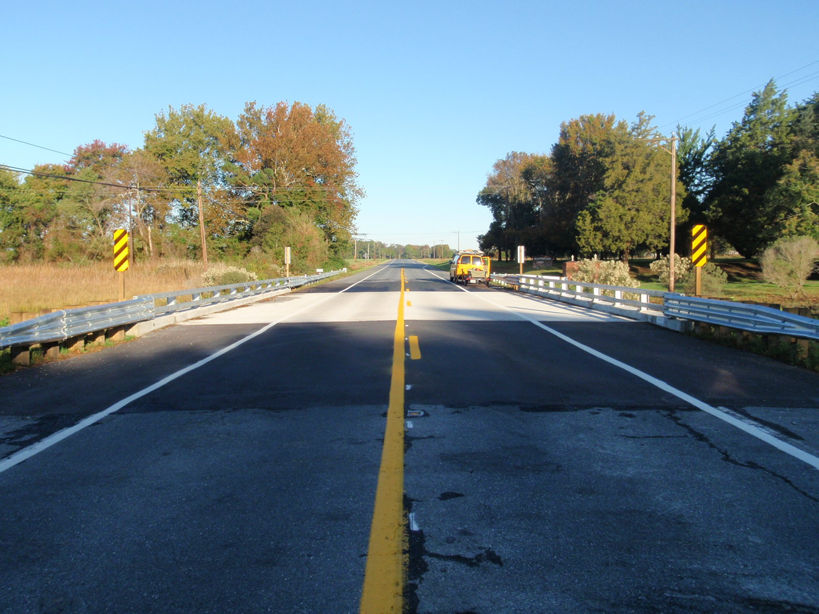
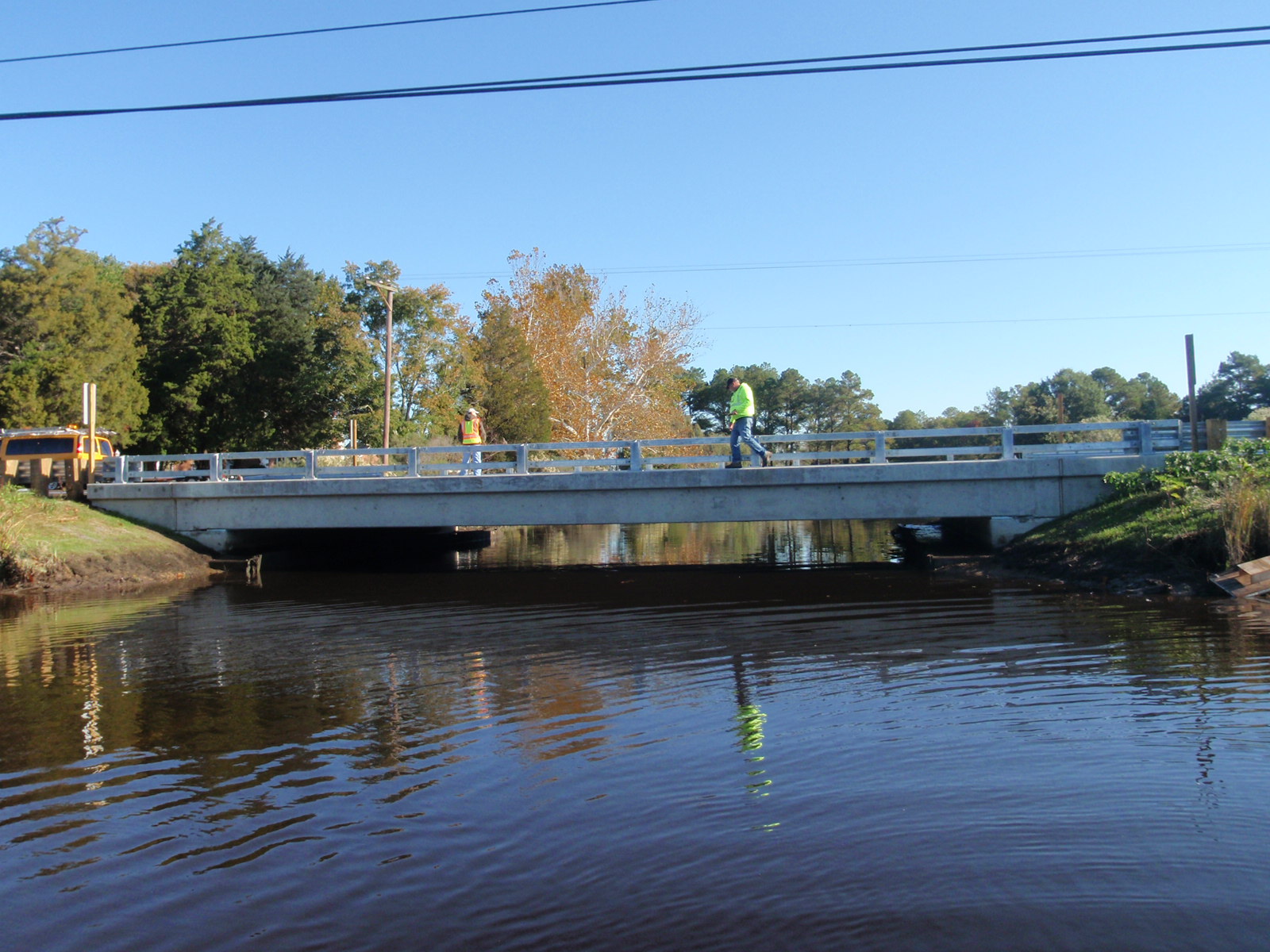
on MD Route 362 (Mount Vernon Road, a rural major collector) over Monie Creek in Somerset County near the town of Jason
Impact Category:
Tier 5 (within 3 months)
Mobility Impact Time:
ABC: 37-day closure (5 weeks plus 2 days); Conventional: 10 weeks for <55-ft spans
Primary Drivers:
reduced traffic impacts; reduced onsite construction time; improved site constructability; improved material quality and product durability; reduced life-cycle cost
Dimensions:
55-ft-long and 45-ft-wide single-span prestressed concrete slab bridge
Average Daily Traffic (at time of construction):
2800
Traffic Management (if constructed conventionally):
Traffic management alternative, if constructed conventionally: extended use of 7-mile detour for low-weight vehicles (13.7 miles for trucks).
Existing Bridge Description:
The existing bridge was a 41-ft-long, 48-ft-wide single-span steel beam bridge with timber substructure. Built in 1934 and widened in 1963, the bridge had two 12-ft-wide traffic lanes, and two 12-ft-wide shoulders compared to two 8.5-ft-wide shoulders on the approaches. The substructure was structurally deficient and required replacement.
Replacement or New Bridge:
The replacement bridge has two 12-ft-wide traffic lanes and two 8.5-ft-wide shoulders. The cross-section consists of eleven 4-ft-wide 2.25-ft-deep prestressed concrete solid slab beams that are post-tensioned together transversely, with a 5-inch-thick reinforced cast-in-place modified latex concrete overlay and precast curbs with embedded rods to connect metal railing. The abutments consist of 4-ft-square precast abutment caps on 12.75-ft-diameter steel pipe piles, and precast wings. The MDSHA gave the contractor several options for constructing the abutments in pieces to allow weights of abutment sections to be no greater than slab beam weights.
Construction Method:
The contractor chose to precast the abutment caps in half-sections with cast-in-place closure joints between the two cap sections and between the precast cap and wingwalls. The contractor chose the option of precast wingwall caps for the lower portion of the wingwalls, combined with cast-in-place wingwall stems.
The abutment caps were cast with partial-depth pockets for the piles to fit into, and circular pipes that extend from the top of the pocket to the top surface of the cap for completion of the closure joints. The caps were cast with threaded inserts in the top of the pockets to allow connection of development reinforcement in the field. The use of threaded inserts simplified fabrication and allowed the caps to be shipped upright instead of upside-down, eliminating the additional step and complexity of flipping the caps in the field.
The contractor drove the piles using single-lane weekend closures prior to closing the bridge. The piles were driven in a single row with a 6-inch tolerance to create a full-moment connection between the piles and abutment while allowing some movement. Steel caps were field-welded on top of the piles and covered with asphalt to allow traffic to be maintained.
The bridge was then closed, the superstructure demolished, and the piles excavated. The piles were cut to the correct elevation and filled with concrete to 20 ft below the bottom of footing elevation. A 19-ft-long reinforcement cage was lowered into each pile, and temporary leveling pads were welded to the piles to support the abutment caps. The caps were delivered to the site, and 4-ft-long development bars were threaded into the inserts in the tops of the cap pockets. The caps were then lowered over the piles. Mechanical coupler splices were installed to develop the top and bottom reinforcement that extended from the caps into the 2-ft-wide closure joints. The closure joints and cap pockets were then cast.
Because the bridge was directly against the stream and the ground elevations on site were close to sea level, driven sheet piling was specified in the contract for scour protection. The contractor installed the sheeting after excavation, before the piles were cut at their final elevation, to help dewater the area around the abutment. After the abutment cap was erected, the sheeting was connected to the cap with tie rods placed through preformed holes in the caps. The tie rods connected to a small waler in front of the sheeting. A top mat of reinforcement was placed over the top of the waler and sheeting, and the area between the existing and new abutment was filled with cast-in-place concrete as a cap for the sheeting. The scour protection and abutments were designed as a system, helping to minimize the section requirements of both the piles and the sheeting. After casting the cap, the existing timber abutment was cut off to the top of the cap and the formwork around the wing walls was removed.
The contractor then placed the slab beams, grouted the shear keys between beams, post-tensioned the beams together, and added reinforcement for the cast-in-place overlay. Immediately prior to placing the overlay, the contractor lifted the reinforcement mat with a crane and swept a layer of grout on the beams. This was required to ensure good contact between the beams and latex modified concrete overlay. The contractor then placed the overlay after applying a horizontal bond breaker between the abutment cap and overlay to create a semi-integral connection that allows for the typical ¼-inch movement. While the overlay cured for seven days, the contractor finished casting the wing walls, installed the bridge railing, and did other finish work. The bridge was then opened for traffic.
The contract required the bridge to be closed a maximum of 35 days (five weeks). It included an incentive of $6,000 per day if the bridge was opened in 30 days or less, with a maximum of $30,000. A disincentive of $6,000 per day greater than 35 days was also included. The bridge was completed in 35 days and opened in 37 days, on August 14, the day before the first day of school.
Stakeholder Feedback:
The main construction steps that achieved the shorter timeline were driving the piles with weekend lane closures prior to closing the bridge, minimizing the dewatering requirements by using sheet piling, and using precast abutments and wing walls.
High Performance Material:
Project Planning
Decision Making Tools:Site Procurement:
Project Delivery: Design-bid-build
Contracting: Full lane closure; Incentive / disincentive clauses
Geotechnical Solutions
Foundations & Walls:Rapid Embankment:
Structural Solutions
Prefabricated Bridge Elements: Adjacent slab beams; Precast abutment cap; Precast wingwalls; Steel sheet pilingPrefabricated Bridge Systems:
Miscellaneous Prefabricated: CIP reinforced concrete closure joints; Grouted key closure joints; Bars in splice couplers; PT ducts/bonded; Socket connection (in precast substructure)-(caps); Precast curbs; Latex-modified overlay
Costs & Funding
Costs:The engineer’s estimate for the project was $1.6 million. The low bid was $ 1.7 million ($100,000 = 6% higher than engineer’s estimate). There were 5 bidders (4 bidders selected the precast element options, 1 selected conventional cast-in-place). The cost per square foot of bridge was $308 compared to $280 for conventional construction in this region in 2009.
Funding Source:
Federal and State
Incentive Program:
Additional Information
Downloadable Resources
Contract Plans:Specifications:
View SP021-ProjectDescription-projd-082808.doc
View SP022-IncentiveDisincentive-esf-final-082808.doc
View SP022-NoticeToContractor-obd-011008-final-082808.doc
Construction Schedule:
Other Related Information:
2010-FHWA-MD-362-Monie
Summary Sheet:
2010-FHWA-MD-362-Monie
120330-ABC_New2_MD-362-over-Monie-Creek
Other Related URLs:
Maryland State Highway Administration
Contacts
Jeffrey Robert, P.E.
Senior Project Engineer, Office of Structures
Maryland State Highway Administration
jrobert@sha.state.md.us
410-545-8327