
State: NC
County:
Owner: State
Location: Urban
Spans: > Three-span
Beam material: Concrete
Max Span Length (ft.): 33
Total Bridge Length (ft.): 495
Construction Equipment Category: Conventional
ABC Construction Equipment: Conventional
State ID Number: 150110
NBI Number: 310110
Coordinates
Latitude: 34.7237778 | Longitude: -76.6931076


Bridge Description
Project Summary:Project Location:
US Highway 70 over Newport River between Morehead City and Radio Island in Carteret County
Impact Category:
Tier 3 (within 2 weeks)
Mobility Impact Time:
ABC: Weekly track closure of 4-day duration; Conventional: ABC is conventional for railroads
Primary Drivers:
reduced traffic impacts; reduced onsite construction time – the trestle was replaced while serving rail traffic, with individual spans replaced between scheduled trains; improved site constructability
Dimensions:
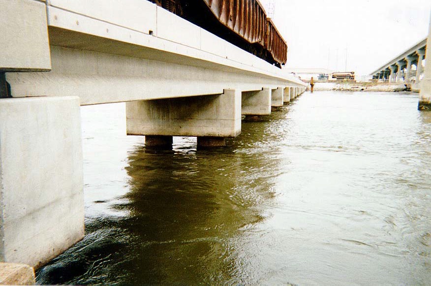
495-ft-long (15 spans @ 33 ft) 12-ft-wide prestressed concrete adjacent T beam trestle-span approaches on the west side of the bascule span and 1,749-ft-long (53 spans @ 33 ft) 12-ft-wide prestressed concrete tee-beam trestle-span approaches on the east side of
Average Daily Traffic (at time of construction):
0
Traffic Management (if constructed conventionally):
Traffic management alternative, if constructed conventionally: railroads require ABC, to limit downtime
Existing Bridge Description:
The existing railroad bridge consisted of 85 trestle-span approaches on the west side and 310 trestle-span approaches on the east side of a single-leaf rolling bascule span. Built in 1960, the trestle-span approaches were deteriorated and required replacement.
Replacement or New Bridge:
The ballasted, trestle-span cross-section consists of two 6-ft-wide 3-ft-deep precast prestressed concrete tee-beams. The tee-beams are supported on precast reinforced concrete caps on composite piles (24-inch steel pipe piles protected by 36-inch concrete cylinder pile sleeves). The bridge was designed and constructed to AREMA standards and to meet NCDOT’s highly-corrosive coastal environment criteria. All environmental documentation and permits, design, construction, and construction engineering were done by the design-build team.
Construction Method:
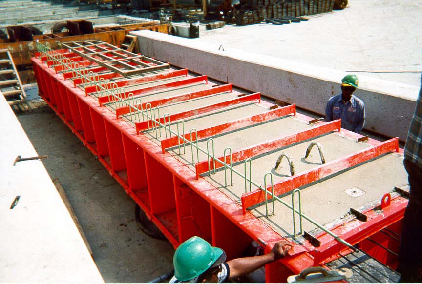
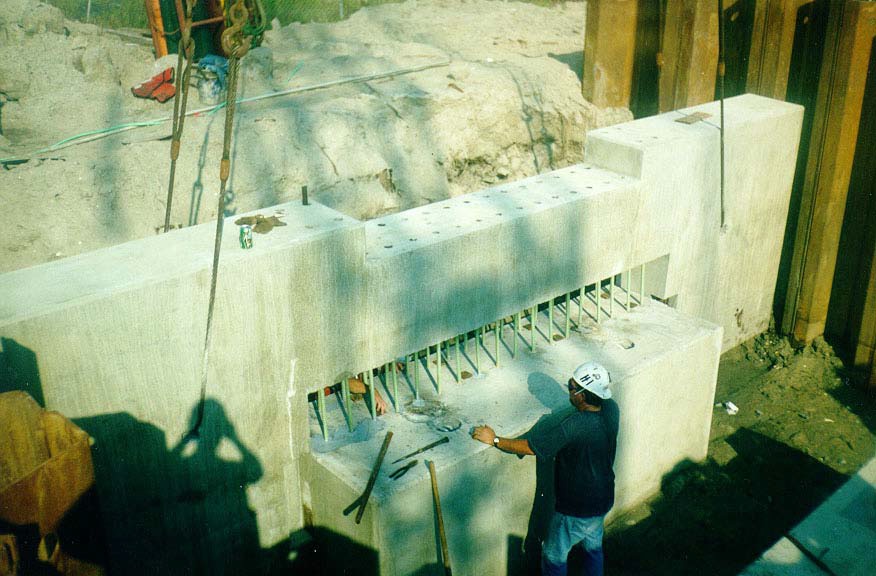
The project replaced the trestle-span approaches on existing alignment during weekly track closures of 4-day duration between scheduled trains. Approximately 99 ft of existing trestle was removed, two bents constructed, three spans erected, ballast placed and rails attached during every 4-day track closure.The contractor fabricated the pretensioned concrete tee-beams in a precast yard near the bridge site. The tee-beam shape was chosen by the contractor for ease of handling and to make use of available forms. The parapets were cast onto the beams at the precast yard after release of the prestressing strands. The precast pile caps were cast upside down with pile reinforcement extending from the cap, and with tapered voids formed inside the pile reinforcement to allow concrete to be pumped into the pile to make the moment connection between the cap and pile. Other precast elements included flat slab transition spans at the abutments and at the transition to bascule rest piers, and precast thrust block ribs.The contractor used templates and a vibratory hammer to drive the 24-inch-diameter steel pipe piles. The 36-inch-diameter concrete cylinder piles were then driven over the steel pipe piles to three feet below scour depth to provide corrosion protection. Grout was pumped in the annular void between the two piles. The caps were erected with the pile reinforcement extending from the cap, and the caps were lowered onto the piles. Concrete was pumped into the cap and pile voids to make the moment connection between the cap and the pile. The precast abutment caps were erected on the piles, and the precast backwalls and wingwalls were erected atop the caps. The embedded structural plates on the backside of the abutment cap and wings were overlapped, welded together, and covered by grout to make the abutment a continuous structural element. Elastomeric bearing pads were placed, and the beams were erected onto the pads. Anchor bolts, connecting the tee-beams to the precast caps were installed and grouted. A fiberglass ballast stop was placed in the joint between the tee-beam flanges.The contract specified completion in 365 consecutive calendar days after the date of availability, with a completion date no later than March 14, 1999. The contract specified liquidated damages of $750 per calendar day for final completion. No incentives were offered for early completion.
Stakeholder Feedback:
High Performance Material:
Project Planning
Decision Making Tools:Site Procurement:
Project Delivery: Design-build
Contracting: Full lane closure (i.e., full track closure)
Geotechnical Solutions
Foundations & Walls:Rapid Embankment:
Structural Solutions
Prefabricated Bridge Elements: Adjacent T beams; Precast pile caps; Precast abutment caps; Precast backwalls; Precast wingwallsPrefabricated Bridge Systems:
Miscellaneous Prefabricated: Pocket connection (in precast substructure); Prefabricated railing; Other miscellaneous element – precast flat slab transition spans and thrust block ribs
Costs & Funding
Costs:The engineer’s estimate for the project was $4.00 million. The low bid was $6.94 million (73% higher than engineer’s estimate; however, the percentage was reduced once technical scoring was applied to the bids). There were three bidders. The cost per square foot of bridge was $253 compared to $95 for conventional construction in this region in 1999.
Funding Source:
State Only
Incentive Program:
Additional Information
Downloadable Resources
Contract Plans: View Carteret-Number110-As-Built-Plans.pdf
View Carteret-Number110-Contract-Plans.pdf
View Carteret-Number110-Specifications.pdf
Construction Schedule:
Other Related Information:
North Carolina Department of Transportation
Contacts
Brian C. Hanks, P.E.
Project Engineer
North Carolina Department of Transportation
bhanks@ncdot.gov
919-707-6419