
State: UT
County:
Owner: State
Location: Urban
Spans: Two-span
Beam material: Steel
Max Span Length (ft.): 76.5
Total Bridge Length (ft.): 155.5
Construction Equipment Category: Conventional
ABC Construction Equipment: Conventional
State ID Number: SP0026(4)0-B
NBI Number: 0C-966
Coordinates
Latitude: 41.1748962 | Longitude: -100

Bridge Description
Project Summary:Project Location:
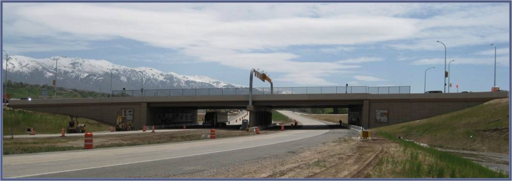
Riverdale Road over I-84 in the city of Riverdale in Weber County
Impact Category:
Tier 1 (within 1 day)
Mobility Impact Time:
ABC: no reduction in number of lanes during construction ; Conventional: estimated 8 months (4 months per phase), plus winter weather delays
Primary Drivers:
reduced traffic impacts – reduced traffic impact time; reduced onsite construction time – reduced impacts to local businesses during important retail period (Thanksgiving to Christmas); improved work-zone safety (through reduced time on construction site)
Dimensions:
155.5-ft-long and 170.83-ft-wide two-span steel plate-girder bridge (76.5 ft – 76.5 ft); 5º skew
Average Daily Traffic (at time of construction):
31475
Traffic Management (if constructed conventionally):
Traffic management alternative, if constructed conventionally: extended use of reduced lane and shoulder widths and lane shifts
Existing Bridge Description:
The existing two-span reinforced concrete beam bridge was 203-ft long and 76-ft wide with concrete substructure founded on piles. It had four 12-ft-wide traffic lanes, a 10-ft-wide left-turn lane, a 4-ft-wide central median, and two 3-ft-wide shoulders. Built in 1967, the bridge was deteriorated and required replacement.
Replacement or New Bridge:
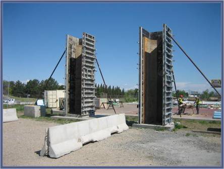
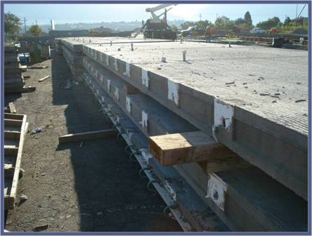
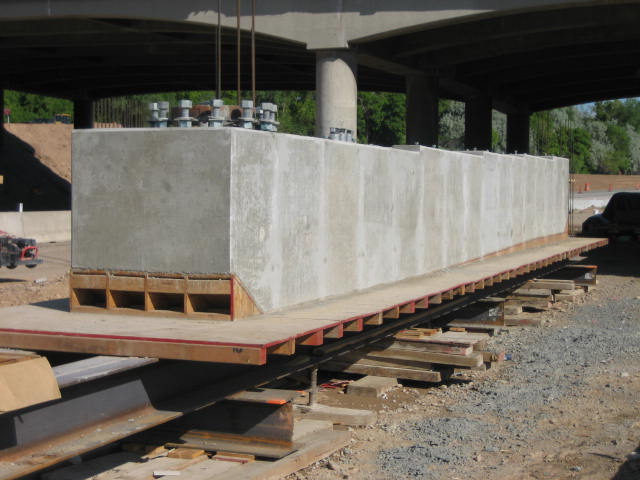
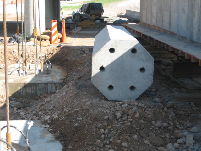
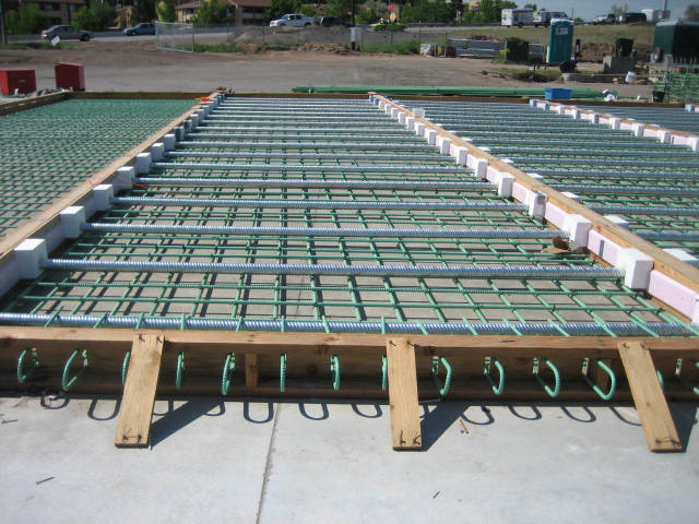
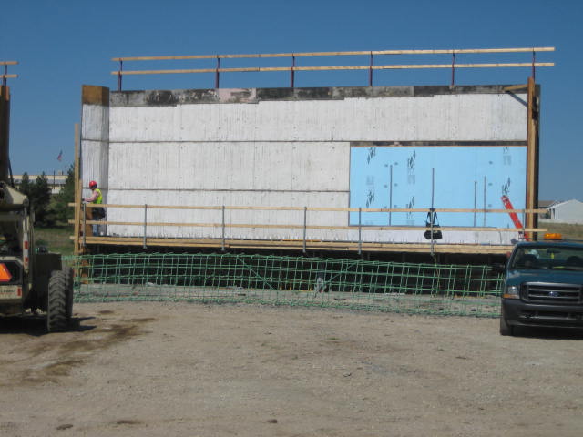
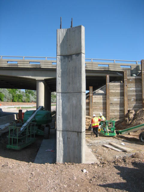
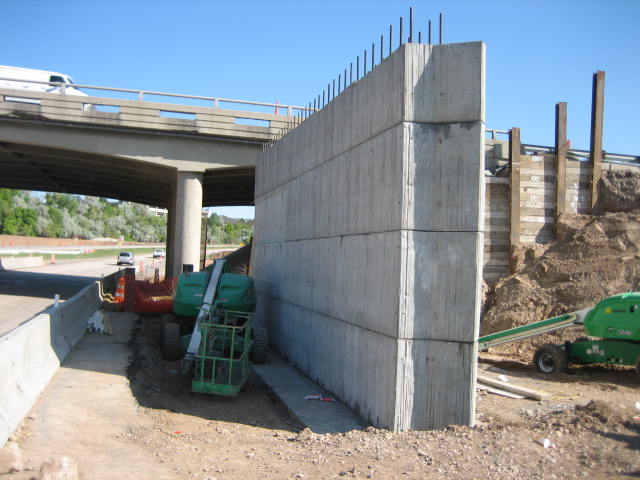
The replacement bridge accommodates a Single Point Urban Interchange (SPUI). It has six 12-ft-wide traffic lanes, two 12-ft-wide turning lanes, two 4-ft-wide minimum shoulders, and two 6-ft-wide sidewalks. The cross-section consists of twenty 3-ft-deep steel plate girders spaced at 8.67-ft with an 8.25-inch-thick non-composite full-depth precast deck. The precast abutments are founded on steel HP 14×102 piles. The interior pier consists of four separate precast caps, each supported on two precast columns, also founded on steel HP piles. Other prefabricated elements include precast end diaphragms and precast approach slabs.Mechanically-stabilized earth (MSE) wall abutments were used for the bridge. The MSE walls used lightweight fill to minimize settlement and avoid surcharging. This reduction in settlement accommodated the phased construction better and significantly reduced the project schedule by eliminating surcharge time.
Construction Method:
The new bridge was designed much larger than the existing structure to limit impacts. Part of the minimize-impact strategy was to make an oversized square SPUI instead of an hour-glass SPUI bridge to accommodate the phased construction and traffic with minimal impacts. The contractor match-cast the prefabricated elements at an onsite casting yard. The bridge remained open throughout construction, which consisted of two phases. In Phase I, two 42.21-ft-wide bridges were constructed on either side of the existing bridge while traffic was maintained on the existing bridge. In Phase 2, traffic was shifted to the new bridges, the existing bridge was demolished, and the middle half of the new bridge was built and connected to the Phase I bridges. In Phase 1, piles were driven. Post-tensioning bars and ducts, dead anchor accessories, and anchorage zone reinforcement were placed in the footing forms. The footing reinforcement was placed, and the footings were cast. After footing strength was achieved, the abutment stems were erected over the embedded post-tensioning bars in the footings. Adjoining faces were epoxy coated prior to erection. After the top segment was erected and the epoxy reached strength, the vertical post-tensioning strands were stressed and duct connections were grouted.The precast columns were erected onto the cast-in-place footings and similarly connected to the footings. The precast caps were erected and post-tensioned to the columns, and the steel plate-girders were erected on the caps. The non-composite precast deck panels were erected onto neoprene foam strips on the edges of the top flanges of the girders; there were no shear studs connecting the panels to the girders. The longitudinal post-tensioning ducts, spaced at 2.5 ft across the deck width, were coupled and tendons were threaded through the ducts. The transverse deck joints were grouted. The longitudinal post-tensioning tendons were stressed and ducts were grouted. Haunches over the girder flanges were grouted. The precast end diaphragms were then bolted onto the backs of the girders. The precast approach slabs were placed, and a closure joint was cast to connect the deck, end diaphragm, and approach slabs. Bridge parapets and sidewalks were cast.In Phase 2, traffic was then switched to the two new outside bridges, the existing bridge was demolished, and the middle half of the bridge was constructed, tying the two outside bridges together and forming the final cross-section. The abutment closure joints and the longitudinal closure joints were cast. A polymer concrete overlay was applied and the bridge was opened to traffic. The Construction Manager General Contractor (CMGC) project delivery method was used for this project. The contract required completion by Thanksgiving and included a $60,000 disincentive if the bridge was not completed by then. The contractor missed the deadline due to roadway and wall schedules behind the bridge. However, the outside segments were completed by Thanksgiving, and this allowed construction activities to stop and the interchange to act as a normal interchange during the shopping season. The contractor paid the disincentive penalty rather than bring in additional workers to finish the roadway, wall, and interior bridge by Thanksgiving. The break after Thanksgiving then allowed time to complete fabrication of the remaining precast elements in the yard. [Before Thanksgiving the construction schedule had been so tight that the precast elements were being taken directly from the precast beds in the yard and erected on the bridge.] When construction resumed in January, the contractor was able to quickly finish the interior section of the bridge.
Stakeholder Feedback:
Lessons learned: (1) Keep an eye on the overall project schedule (roadway and walls), not just the bridge. (2) CMGC was very important and helpful in the development of the precast details and assembly methods. The contractor and designer worked together extensively during the design process. (3) An efficiency gained was that no shop drawings were required. The contractor was able to construct the prefabricated elements in the onsite casting yard using the design plans. (4) The business community was very pleased with the minimal impacts they dealt with.
High Performance Material:
Project Planning
Decision Making Tools: State processSite Procurement:
Project Delivery: CM/GC
Contracting: Full lane closure; Incentive / disincentive clauses
Geotechnical Solutions
Foundations & Walls:Rapid Embankment: Lightweight fill
Structural Solutions
Prefabricated Bridge Elements: Full-depth precast deck panel w/PT; Precast cap & column(s); Precast abutment stems; MSE wallPrefabricated Bridge Systems:
Miscellaneous Prefabricated: CIP reinforced concrete closure joint; Grouted key closure joint; PT ducts/bonded; Match cast closure joint; Epoxy joint; Polymer concrete overlay; Precast approach slab; Precast diaphragm
Costs & Funding
Costs:The low bid was $3.8 million. The cost per square foot of bridge was $143. The non-composite deck detail reduced onsite bridge construction time by several months, equating to a $2 million road user cost savings.
Funding Source:
State Only
Incentive Program:
Additional Information
Downloadable Resources
Contract Plans: View 2495_C-966_Riverdale-Over-I-84.pdf
View 03413S-Precast-Concrete-Stay-In-Place-Form.doc
View 03413S-Precast-Substructure.doc
View 03485S-Precast-Concrete-Approach-Slab-and-Deck-Panels.doc
Construction Schedule:
Other Related Information:
Utah-ABC-Process
Summary Sheet:
130130-ABC_New2_UT_2008_Riverdale_-Road-over-I-84
Other Related URLs:
Go to:
http://www.udot.utah.gov
Utah Department of Transportation
Contacts
Carmen Swanwick, P.E.
Chief Structural Engineer
Utah Department of Transportation
cswanwick@utah.gov
801-965-4981